As a kid, I used to spend a lot of time inventing and building electronic circuits. I could have told you immediately that yellow-violet-orange meant a 47 kilo-ohm resistor. Alas, those details have slipped into the murky depths of time, but I have regained an interest in electronics recently because I’ve seen how powerful and easy-to-use modern microprocessors are.
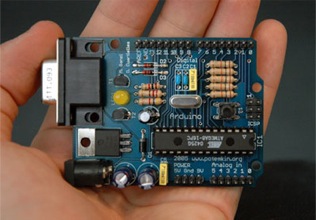
In particular, I’ve been looking into the Arduino microprocessor (shown right) as the core of a few applications I want to build.
But before I leap into more complex projects, I want to re-acquaint myself with building electronic circuits again. All of my electronics gear is back in Australia so I needed to do quite a lot of shopping to get myself all set up again. After a very long time spent wandering the confusing aisles of Fry’s (the handiest place for this kind of gear, even if not the best), I came home with quite a haul.

As a starting point, I just wanted to have a reliable 5V power supply available for building circuits. This should be easy (and is in hindsight), but it took a while to figure out precisely how to do it. I opted for an off-shelf power adaptor that has a switch to select voltages in 1.5V increments up to 12V.
I grabbed a prototyping breadboard to build the circuits on, and a handful of components to have a properly regulated power supply. The cheap power adaptor has settings for 4.5V and 6V but nothing for 5V so I definitely needed to do something to give a reliable 5V supply. Of course, those settings are very loose as it is and if you measure the voltage across the supply without any load or a very small load, the actual voltage is much higher than that stated.
The first problem was getting power from the power adaptor to the breadboard. I found a convenient socket for a power adaptor cord that I could attach a couple of wires to the back off and run them to the power terminals on the breadboard. That way I didn’t need to hack apart anything in the power adaptor and I can still use it for other purposes.
With power to the breadboard, I just needed to regulate the voltage. The solution was the very convenient LM7805 voltage regulator (which only took me 20 minutes to find at Fry’s because they have a supplier that relabels everything in some obscure code that I only deciphered once finding a full catalog). You can essentially apply any voltage from 7-20 volts or so to the chip, and pull off 5V+/-0.25V. Add a few capacitors on the input and output sides of the chip to smooth out the voltage under load, and it’s all set.
Just to test there was power working properly, I just drove a single LED (via a resistor to avoid the characteristic pungent smell of frying electronics that I recall from undergraduate laboratory classes). And here is the result. As you can see, the LED is lit and my digital multimeter is showing a voltage of 4.99V. A perfect start to getting back into electronics.

Next was a simple circuit to make sure I have things working. Using the classic 555 timer integrated circuit, I decided to make a small sound generator. It produces a sawtooth pattern with the frequency depending on the values of resistors and capacitors in the circuit. I don’t have very many components on hand so I had to steal the capacitors from the voltage regulator for now, and just used the resistors I had to hand, but the frequencies come out in the audible range and different resistors do indeed create different tones.
Yes, this is a pretty boring outcome so far, but it’s amazing how much I am re-learning just in the process of getting all the gear together and setting it up! My Arduino board should be arriving soon, and I have the Processing language installed and I am playing with it so that I can make my computer talk to the microprocessor, all on the way to a fun application I’ll write about as I get further along.